
Millstar Products: Frequently Asked Questions
There are four basic types of tool shapes that find extensive use in profile and three-dimensional milling: square end with sharp corners, square end with small or larger corner radii (also known as bull nose), toroid (square or back-drafted tools with each corner radius approximately 25% of the tool diameter) and ball nose cutters. Millstar has developed a number of milling strategies which successfully apply all of these tool types depending on the shape of the part and the type of cut and tool engagement.
Some of the processes Millstar developed are opposite to conventional practice. For example, Millstar will machine an open ended or closed, deeper slot by employing a ball nose tool and using typical High Speed shallow ramp and Z-level milling techniques; the slot will be produced far faster than milling with a cylindrical end mill. The sidewalls will be straight and perpendicular, and not tapered as they often are with long end mills due to tool deflection. Ribs can be processed in similar fashion. A typical application was milling 3/4" wide slots in mold bases, 5" long and 2" deep. There was a cross hole in the middle of the part creating an interrupted cut. 6 slots were originally finish milled in 30 minutes, not including roughing time. With the new High Speed technique, 6 slots were roughed and finished in one combined operation in only 10 minutes. Link to Tech. Article "High Speed in the Slots". Millstar has developed many other innovative processes. We will be glad to share them with you.
Long reach milling applications put high demands on tool holders: high rigidity and tool stiffness. Another parameter requirement is a shallower depth of cut. In long reach operations the tool will always stick out more than normal out of the tool adapter. Long reach is defined as a tool extending from the adapter by more than 4 times the tool / shank diameter. Steel tool holders are useful and work fine when extending no more than 3-4 times the tool diameter. Longer tool extension with steel holders requires a reduction of the recommended milling parameters.
Steel tool holders with stronger tapered nose and larger tool shank diameters can be used instead of cylindrical tool holders. The rule of thumb is that an increase of the shank diameter to the next nominal size (as is the case with switching from a cylindrical to a tapered holder) or approx. 20% tool shank diameter increase will decrease the deflection of the tool shank by approx. 50%. If this increased stiffness is not sufficient (deflection too high or surface finish too rough), then solid carbide tool holders or carbide extensions with screw-on tool heads can be the answer. These tools have the highest stiffness available. Their stiffness is far higher than carbide core or heavy metal tool holders; they are shrink-fit compatible and suitable for High Speed milling.
Hard milling applications put high demands on tool holder and cutting edge and requires certain adjustments to milling parameters. Fully hardened material is harder to cut and the cutter will develop more heat in the cut. By using ball nose tools wherever possible, the detrimental influence of heat can be minimized. Cutting speed and consequently the feed rate have to be reduced. Depth of cut and consequently width of cut or step-over will also have to be reduced when milling hard material.
Due to the additional chip thinning effect caused by the shallower depth of cut, the tool can be run at a higher feed per tooth (fz) and the feed rate decrease is small or even offset. Toroid tools, bull nose tools and square tools may also be used in hard milling operations, but the sharper the corner radius, the less 'heat-defying' the tool is. Contact our application specialists with your specific questions or applications.
Die/mold milling and other high performance milling applications put high demands on cutting tool and tool holder materials. Rigid tools will reward the user with increased metal removal, better surface finish and accuracy, and longer tool life to name just a few benefits. When using insert technology, steel tool holders are usually adequate for tool extensions to four times extension to tool or shank diameter (whichever is larger). Steel tool holders may be used up to seven times tool extension to tool / shank diameter with reasonable milling results, but care must be taken to reduce machining parameters.When milling with a long tool extension the use of solid carbide tool shank material is recommended. Carbide has the highest bending strength of any shank material. In High Speed (HS) applications the use of solid carbide, balanced tool holders is also highly recommended. Some suppliers of machine tools with machine spindles that reach > 40,000 RPM spindle velocity will not warrant their machines, if tools with other than solid carbide shanks are used. It is a very important safety consideration. A recent ISO standard #ISO 15641 entitled 'Milling cutters for high speed machining – Safety requirements' deals with the safety of tools and the possible hazards arising from their use in High Speed applications. It is a good resource regarding safety.
Insert technology for die/mold making and general machining applications has been enhanced to a level that it can perform most operations without fail. Many operations can be performed with insert tooling, especially in medium to large cavities and cores, since the diameter of insert tooling available fits well into this category. Insert tooling, from diameter of ½ inch (12mm) and larger, work very well for roughing and finishing applications. The smaller insert diameters are designed mainly for finishing applications and some lighter duty roughing.
There are still certain applications areas where solid carbide tooling has advantages. The most obvious time to select solid carbide tools is when the diameter is less than ¼ inch (6mm) diameter. Insert technology has not been developed for the smaller diameters. One of the newer processes called trochoidal milling is another application for choosing solid carbide end mills. Trochoidal milling is an application that is used mainly for slot machining but some CAM software developers are using this application for cavity milling as well. This process entails machining with a large depth of cut and very small step over. The machining motion is a very smooth arcing loop cut that moves forward by an amount roughly equal to the step over amount for each loop. A solid carbide end mill is used since it has multiple flutes to maximize the feedrate. Typically this tool is also a high helix tool. This allows for very smooth cutting and the ability to create very good surface finishes. A drawback to this milling strategy is deflection if the tool is long. You may consider an alternative milling strategy used by Millstar for high speed milling of slots.
The old theory that the extension length to cutting diameter ratio plays a deciding role in choosing solid carbide vs. insert tools is now being challenged with the introduction of Millstar’s new solid carbide shanks for insert tooling. There is now very little reason to use solid carbide end mills in diameters exceeding ½ inch (12mm). Before this technology a steel shank tool holder did not have the rigidity required to aggressively machine with long tool extension. Now a carbide shank tool holder with a relatively inexpensive insert can be used in these applications, rather than using a more costly solid carbide end mill. Additional advantages of insert technology include flexibility, repeatability and longer reach.
When using small diameter tools in die mold milling, particularly in HS (High Speed) applications, Millstar's coated solid carbide tools with sharp cutting edges are suitable for milling any of the types of aluminum used in die/mold applications. When using larger diameter tools (3/8" / 10 mm and larger) Millstar's insert technology tools with high positive cutting geometry are a very economical, high performance alternative to solid carbide tools. Use TiCN coated inserts for better tool life; uncoated inserts may also be used.
Stainless steels AISI series 300 (Chrome-Nickel alloys), AISI series 400 (Chrome and Chrome-Molybdenum alloys) and precipitation-hardening (PH) stainless steels can be milled with strategies, parameters and standard catalog tools developed by Millstar for die/mold milling. For most applications AlTiN-Exalon coated tools will enhance the milling performance substantially. For applications with extreme working parameters, contact our application department for a tailor-made solution. The tools best suited are the versatile standard catalog solid carbide end mill series from Millstar, and the Millstar insert technology tools. Inserts with chip- breaker should be used on stainless steel below 40 HRc; non-chip-breaker inserts should be used at 40HRc and higher hardness.
When machining softer, gummy or sticky materials such as stainless or lower carbon steels, a certain amount of lubricant is of advantage in preventing edge build-up. Coolant with a higher coolant concentration (9-12%) or MQL is recommended. Running tools aggressively, so the temperature in the cutting zone is high enough to prevent built-up edge, eliminates this problem and increases productivity as well.
Millstar’s high performance cutting tooling with AlTiN-Exalon tool coating, developed by Millstar for die/mold milling applications, are very successfully used in Aerospace materials such as Inconel, Hastelloy, Waspaloy, etc. Use conventional or High Speed machining strategies. The use of coolant with a higher coolant concentration (9-12%) or MQL is recommended. The tools best suited are the versatile standard catalog solid carbide end mill series from Millstar, and the Millstar insert technology tools. Use of inserts with chip-breaker is recommended.
ISO / CAT / BT taper shanks are still the most widely used tool adapter shank configuration in conventional use. A quality adapter from a reliable supplier will be sufficient to produce good machining results. Take care in selecting adapters that have been pre-balanced by machining to remove any unbalance, or by specifying adapters with balancing features (balancing screws, weights). The majority of machine tools sold with spindle speeds of 20,000 RPM or above now are equipped with HSK spindles. When planning to use adapters for High Speed machining, the selection process becomes more critical. Minimal tool run-out and imbalance are important, as are the type and size of adapter. V-flange type ISO/CAT/BT #40 spindles and tool adapters have usually been the choice for machines used in HS machining.
Lately, with the introduction of the hollow shank HSK tool adapter, this type of adapter has seen far more use and acceptance due to the added rigidity at higher spindle velocities. At high spindle speeds the high centrifugal forces tend to expand the spindle bore slightly. At the large end of the bore the widening tends to be slightly larger than at the smaller interior end. This has a negative effect on the seating accuracy, run-out and balance of the tool adapter. It may also cause the tool to be stuck in the spindle after spindle rotation has stopped. HSK adapters with hollow shank are designed to widen with the spindle bore during high rotational speeds and maintain full radial surface contact; axial face contact also remains and prevents the tool from being pulled up into the spindle. HSK tool adapters are ideal for High Speed and aggressive milling applications.
Causes for unbalance in tool adapters include flaws or voids in the adapter material, poor finish and out-of-roundness in the machining process of adapter features, eccentricity of through-holes on the rotational axis, or machining features that reduce the absolute concentricity or symmetry of the adapter. Additional causes for unbalance are of a design nature: asymmetrical features such as drive slots, setscrews on end mill holders, the notch for tool orientation in DIN V-flange adapters and even unbalanced retention knobs. Unbalanced cutting tools or tool holders may also add significantly to the imbalance of the cutting tool and tool adapter assembly. One example of imbalance in tools is the Weldon screw flats on tool shanks.
Out-of-balance forces increase quadratically with increase in rotational speed. A rule of thumb is that the centrifugal force of a tool and adapter assembly running at 2,000 RPM will increase to 25 times at 10,000 RPM, and to 100 times at 20,000 RPM. Looking at unbalance another way, one ounce/inch (72 gram/cm) at 1,000 RPM equals 1 pound centrifugal force, 16 pounds at 30,00RPM, 65 pounds at 6,000 RPM, 180 pounds at 10,000 RPM and 400 pounds at 15,000 RPM. Tool stiffness and bending strength of steel and even solid carbide tool holders have a limit. Tool assembly balancing is a must for successful milling results at high spindle velocity.
One international standard (ISO standard #ISO 15641 entitled “Milling cutters for high speed machining – Safety requirements”) states that “for safety reasons a milling cutter shall have a balance quality grade equal or better than G 40 in accordance with ISO 1940-1: 1986 at the maximum rotational speed”. For machining performance (improved surface finish results, minimized vibration, extended tool life) it is important however to balance the tool and adapter assembly to a better quality (e.g. G 6.3, G 2.5). The higher the spindle speed, the better the quality needs to be. Millstar has taken great care in designing insert tools and tool holders that are symmetrical and inherently balanced. If tool adapters have been balanced, it often becomes unnecessary to re-balance the assembly, particularly if the tool adapter is heavier than the Millstar tool holder. A balance check is recommended.
For tool holders and spindles there are 3 types of imbalance: single plane, double plane and dynamic imbalance. Single plane imbalance is like an off-center weight. It requires an equal counter weight for correction. Two-plane imbalance is best explained as a wobble imbalance and needs at least 2 counterweights for correction. One- and two-plane imbalance together on the same tool assembly is dynamic imbalance. At the higher spindle speeds employed in HS milling, two-plane balancing will result in better machining results and is recommended.
Millstar has taken great care in designing insert tools and tool holders that are symmetrical and inherently balanced. Unfortunately, the design of many tool adapters is unbalanced. One of the few exceptions is balanced shrink-fit tooling, where the symmetrical tool holder is heated at the nose end of the tool and the bore expands to accept the tool shank. As the nose end cools, the tool shrinks around the tool shank and clamps it firmly and concentrically. This method of clamping is ideal for HS machining, as it provides high torque transmission, minimal run-out and flexible assembly length. All Millstar carbide shanks and solid carbide tools are shrink-fit compatible.
Other options for concentric, balanced tool holding include hydraulic tool adapters, precision collet chucks for small diameter tool shanks, and high pressure mechanical milling chucks for larger shank diameters. End mill adapters are not recommended; the offset and eccentricity caused by the radial clamping screws will cause run-out and imbalance.
Modern coated carbide cutting tools do not need cutting fluids during milling of most die/mold materials. They perform as well or better without coolant. Tool life and reliability do not suffer. When High Speed milling, higher cutting speeds and feedrates create higher friction and heat in the cutting area. Cutting fluid that is directed into the cutting zone instantly vaporizes and any cooling effect is lost. Using extreme pressure to direct coolant into the cutting zone is only useful to aid chip evacuation, but the practice increases the temperature variations and thermal shock as the cutting edge moves in and out of the cut. High-pressure air will accomplish chip evacuation just as well and without the negative thermal shock.
A concept that has been gaining acceptance is the concept of Near Dry Machining, also known as MQL (Minimal Quantity Lubrication). It takes on added importance in today’s environment, where even airborne mist of liquid coolants must be captured and treated as hazardous waste. MQL, which avoids oil on the floor, mist in the air and wet coolant on the chips and work piece, has an appeal to every cost-conscious and environmentally sensitive shop. According to Unist, Inc. (Grand Rapids, MI), a supplier of MQL technology, near dry machining can be done with either water-based or neat fluids. Unist opts for a pure, high efficiency vegetable derivative that by nature is polar when exposed to heat. It migrates to the higher heat areas and then lubricates and evaporates, supplemented by compressed air cooling. Lubricant consumption is about one fluid ounce (0.03 liters) per eight hours.
When using coated tools or inserts a thin PVD coating is preferable to a thick coating. A thin coating will withstand mechanical and thermal stress and tension better.
When machining softer, gummy or sticky materials such as stainless or lower carbon steels, a certain amount of lubricant is of advantage in preventing edge build-up. Coolant with a higher coolant concentration (9-12%) or MQL is recommended. Running tools aggressively, so the temperature in the cutting zone is high enough to prevent built-up edge condition, eliminates this problem and increases productivity as well.
Today’s advanced tool coatings on modern cemented carbide substrates can withstand the extreme cutting conditions found in High Speed and Hard milling. If high productivity, geometric accuracy, economical tool life, consistency and reliability are requirements, these coatings should be considered. TiN and even most TiCN coatings are not capable of running as economically under these cutting conditions. TiAlN and AlTiN coatings have the best heat-defying and wear resistant properties among modern PVD thin-film coatings. Millstar has developed its own proprietary AlTiN-EXALON™ coating that performs as well in softer and gummier materials as it does under extreme conditions in HSM and hard milling to 68 HRC hardness.
For softer, gummy or sticky materials such as stainless or lower carbon steels, and for aerospace materials like Titanium, Inconel, Hastelloy, Waspaloy Millstar has developed a thin-film coating that minimizes edge build-up and can perform under extreme conditions and with long tool life.
Maximum spindle RPM is probably the first question to come up when discussing High Speed machining. Many people feel that when more spindle speed is available at the spindle, faster machining is possible. This often holds true, but is not always the case. More RPM leads to less horsepower available at the spindle to drive the cutting tool. At some point the horsepower required for larger diameter tools will not be available.
RPM required is also directly related to the work piece geometry and motion control capability of the machine tool. If part geometry requires frequent directional changes and rapid acceleration / deceleration, the sustainable feedrate will be slower; spindle speed required will also be slower. We suggest looking at the overall picture of what your plant plans to accomplish with the machine tool now and in the foreseeable future and make an informed choice.
If you produce large molds and use large tools you will probably not want to exceed a 20,000-RPM spindle, but will want to have a machine with an ISO/CAT/BT #50 spindle taper or equivalent, for example HSK 100A.
If you are machining medium and smaller components and plan to use tooling ¾ inch (20mm) diameter and smaller tools, than you should probably end up with a maximum spindle RPM of 25,000 to no more than 40,000-RPM, and a spindle taper ISO/CAT/BT #40 or equivalent, for example HSK 63A or E, or HSK 80F. A comparison table of relative sizes of HSK to ISO/CAT/BT is shown below.
If you are machining with very small tools 3/8 inch (10mm) and smaller than the maximum RPM is limited only to the spindle manufacturers abilities.
The spindle horsepower necessary for High Speed cutting is determined by the diameter and style of tooling you consider using. There must be enough available horsepower to drive all cutting tools that you are planning to use on the material you plan to machine and for the machining process (rough, finish, etc.) you plan to use. High Speed cutting uses less spindle power than conventional milling cuts.
Your spindle supplier will be able to advise you what the maximum diameter is for the style of cutting tools you wish to use.
Most machine tool builders will display the maximum feedrate available on their machines. It is the maximum rate at which the machine is able to move its axes without damage. It is not necessarily the rate at which you will be able to machine a particular part. Look-ahead capability of the machine control among other factors will limit the speed of movement.
Many people will look at the feedrate capabilities of a machine and will be impressed that the catalog specifications, for example, list 2,000 inches (50 m) per minute feedrate maximum. If you are machining mold steels with face mills or large diameter tooling, or any tool for that matter, there will be very few applications that will allow you to use this feedrate while actually cutting the material. The feedrate for a given tool is determined by many more factors than just the motion of the machine. You must determine the diameter and type of tooling, the machining strategy, spindle RPM required, as well as the type of material and parts geometry to be machined in order to know what realistic maximum, sustainable machine tool parameters your shop requires.
In High Speed machining a rigid and stable foundation is required for good machining results. High Speed machining can create high forces and strain on the machine. It also creates a lot of heat that must be dispersed through the machine foundation. There are many different theories on the best way to control the heat generated. One of the most popular is running coolant kept at constant temperature through the ball screws and castings of the machine. This helps control the heat and machine expansion. It also helps to produce the most accurate parts by maintaining the most consistent temperatures in the machine and preventing thermal expansion of any part of the machine. Unchecked heat will create movement in the machine foundation, which will result in less accurate parts being produced.
Spindle growth will occur because of the heat that is generated from the bearings and other moving components inside the spindle. As the spindle RPM increases the heat increases. It is essential to have a cooling system built into and / or around the spindle to control the heat. Spindle growth will have a direct impact on parts accuracy and surface quality.
Inserting the tool path into the control of the machine is a matter that is determined by the manufacturer of the control. There are many methods by which to communicate to the control: floppy discs, CD, Intranet, Ethernet, etc. The best method is determined primarily by the size of programs that are to be downloaded into the control. Many finish tool paths are much too large for a floppy disc. Newer controls today are directly linked to the CAM system via Ethernet or Intranet. This type of download system is not limited by program size and is quite quick to load programs.
The program size is determined by the CAM system and process that is used. A tool path of 10 megabytes or larger is not uncommon. For obvious reasons the machine control must have a large program storage capability such as a hard drive. If no hard drive is available then the use of DNC will be required for any program that is too large to fit into the memory of the control.
In die/mold finishing operations the program tolerance can be as low as .00004* (0.001 mm) and this can create very large programs.
There are many things to look out for in order to be successful when HS machining. The control processor needs to be fast enough to keep up with the feedrates required. The control will have to read the program, execute the program as well as look ahead in the program to determine the direction and velocity of the cut. At the same time the control communicates to the machine servos what to do and receive feedback from the servos.
It is essential for the control to look ahead in the program to control the feedrate to match it to drastic directional vector changes at corners or shoulders, or over and under shooting of the tool path will occur. The result will be an inaccurate parts shape. Creating a good surface finish will also be impaired.
Any hesitation in the control due to data starvation will result in "stutter" and will have a negative effect on feedrate, accuracy, surface finish and tool life.
The control must also have the ability to control the acceleration and deceleration of the feedrate. The acceleration rate for the feed mode is at most the same as for the rapid traverse rate. Some machine builders boast of 1G or more acceleration for rapid traverse. Most fail to point out that their feedrate is typically considerably slower. Higher resolution feedback is important in high performance milling applications. The closer the position and velocity of the servo system is monitored, the less opportunity it will have to drift. Some manufacturers use as little as 25,000 pulses while the better builders use up to 1,000,000 feedback pulses for each revolution of the servo motor and ball screw.
Superior physical attributes of the machine, drives and spindle alone are not enough; the machine tool must represent a total, integrated performance machining package which enables the processing of long, complex programs as found in mold finish operations, process them at extremely high speeds, and achieve superior accuracies and finish levels. A CNC control with look-ahead and geometric intelligence, and a high sustained feedrate is needed.
At Millstar we highly recommend milling a typical mold cavity with a ball nose insert tool. This includes cavities with shallow or steep angle and straight (perpendicular) walls. The large radius of a ball nose tool will be able to cut faster than square or bull nose tools; the ball nose insert will create a smoother transition and leave a more even stock for semi-finishing. Square and bull nose tools typically leave “steps” resulting in very uneven stock, causing changing machining forces and increased tool deflection for semi-finishing. Rest milling of small details (small radii, sharp corners, etc.) can be done with other tools once the cavity has been finished with the ball nose tool.
Ball nose tools have other important advantages. They can be run at higher rotational speeds and feedrates than other tools when using milling strategies and parameters developed by Millstar. Whether milling aluminum, annealed steel, pre-hard or through-hardened die/mold steel, we recommend ball nose tools as first choice. The primary strategy we recommend is milling the cavity with a "Z-level" (X – Y contour) tool path. Start the first pass by straight or helical ramping (1-3° ramp angle) to the recommended depth of cut (ap). This allows the feedrate to remain the same as in the Z-level cut. We do not recommend plunging or peck drilling to depth. Preferably work from inside out to the periphery of the cavity in a climb milling (down milling) tool path. In the first pass the tool is engaged in a channel cut and the cutting edges are “in the cut” for 180 degrees. This imparts more heat into the tool, but the channel cut is relatively short. Working from the periphery toward the center, the peripheral first channel cut is far longer; the heat generated is higher and would require the tool to be run slower. The step-over or pitch (ae) for roughing and semi-finishing should follow Millstar recommendations. Typically the step-over in HS rough and semi-finish milling is 20 – 45 % of tool diameter. This keeps the cutting edge “in the cut” for a shorter time and gives the cutting edge less time to heat up. It also keeps the tool “on center” as it cuts on both sides of the tool’s axis and minimizes tool deflection.
We do not recommend drilling starting holes in corners or center of a cavity. They lead to interrupted cutting, possible chip re-cutting and additional cutter entries and exits during cutting, which lead to unnecessary thermal and load shocks on the cutting edge.
In soft or pre-hard materials a ball nose carbide tool or ball nose insert tool can be used. The advantage of the large tool radius is that a good finish can be achieved with a larger step-down. In harder materials a tool with a smaller corner radius (Toroid or bull nose tool or insert) should be used to minimize tool deflection. On steep or straight (perpendicular) walls a back drafted tool should be used. Choose a Z-level or spiral cutter path to keep the cutting edge constantly in the cut. This strategy reduces the number of times the cutting edge of tool or insert goes into or exits the cut and is subjected to a thermal and load shock; it helps to prevent tool life reduction and insert failure.
Millstar recommends down/climb milling for most of Millstar’s tools and recommended milling strategies. Use climb milling as much as possible; tool life is generally longer in climb milling. Climb milling eliminates the rubbing of the tool edge across the material surface encountered when entering into the cut in up or conventional milling. Tool edge rubbing generates much more friction and heat, negatively influencing tool life. In steels tending to surface-harden, up/conventional milling can lead to quick tool failure.
Constant tool pressure is achieved when the cutting parameters in milling are not altered. Rest stock / material allowance is of constant thickness; feed rate, spindle RPM and tool extension are kept constant and therefore chip thickness per tooth also remains constant. Cutting load, tool pressure and consequently tool deflection remain constant. Constant tool pressure is very important in achieving superior finishing results, particularly in HS machining and machining of hardened metals. Mold makers have always tried to eliminate mold polishing as much as possible. To achieve this goal, geometric accuracy and surface finish of the mold must be improved. Constant tool pressure goes a long way to accomplish this goal.
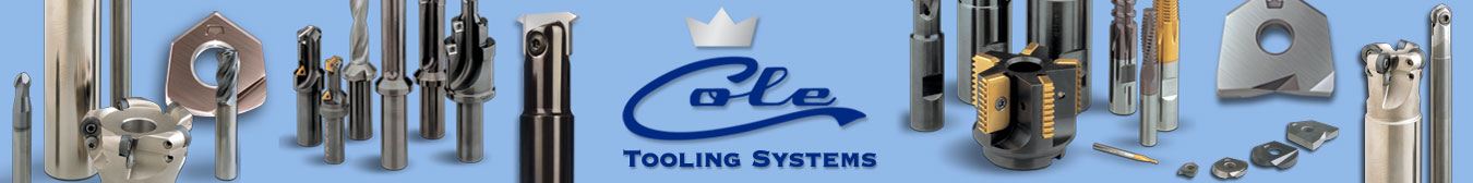
Millstar uses a new High Speed machining approach to mill slots quickly and accurately. The technique allows for deeper and narrower slots, even in fully hardened steels. Typical Millstar High Speed machining Z-level roughing techniques with ramp entry are used, with a shallow depth of cut. Depth of cut in non-heat-treated steel is as much as 10% of the cutter diameter and reduces to 4-5% in fully hardened steels. By using a ball nose or ball insert tool, the feedrate and cutting speed can be increased dramatically when compared to conventional milling methods. Walls of the slot can be machined perfectly straight due to constant tool pressure, contrary to tool bending and deflection in conventional or trochoidal slot milling with cylindrical end mills.
This technique can be employed for open end or closed end slots, through slots or slots with bottom. The ball nose tool will leave a radius at the bottom, which subsequently can be finished to a square bottom with a square or back draft tool. The technique is also useful for odd shapes such as slots with tapered walls, oblong or irregular shaped slots or openings as found in extrusion dies and the like. Cycle-time savings can approach 75%. One example of milling six ¾" wide by 2" deep and 5” long slots on mold bases shows a time reduction from 30 minutes to 10 minutes to mill all six slots.
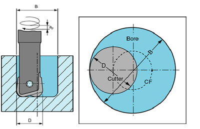
Millstar uses a new High Speed machining approach to mill deep holes or small cavities quickly and accurately. The technique allows for deeper and smaller holes, even in fully hardened steels. When machining soft and pre-hard steels, a ball nose tool is first choice, since the cutting speed and feedrate values can be run at or near High Speed milling parameters. A helical interpolation spiral milling tool path is used. The tool diameter of solid carbide tools should be between 60 and 80% of the hole diameter: insert tools should be between 60 and 90% of the tool diameter. In holes over 3 times depth-to-hole diameter, inserts should be held in carbide tool shanks.
Pictures below show the concept of helical interpolation spiral milling a bore.
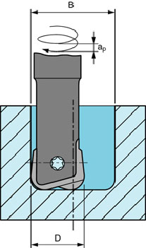
When machining hardened materials, deep holes should be machined with a back draft insert tool to direct the cutting pressure toward the spindle and thereby reduce side pressure and possible vibration.
There are two main causes that can cause chatter in this situation. The first possible cause is that the tool radius is the same size as the corner radius to be machined and the tool path was programmed as a linear move with a right angle turn in the corner. This will cause the tool to be in full contact with the entire radius when it gets to the center of the corner. It can increase the load on the cutter by a factor of three. One option to avoid this problem is to use a smaller diameter tool to form the corner by programming an arc to follow and generate the radius. This keeps the tool from getting buried into the corner. A second option is to use a larger diameter tool and program an arc in the corner that will produce a bigger corner radius with circular interpolation. This technique allows for a bigger diameter tool to be used for roughing, with a higher metal removal rate. The smaller corner radius can later be machined by milling the remaining stock with a smaller cutter and circular interpolation cuts to generate the small radius.
The second possible cause is excessive tool extension. If the tool is too long it can cause vibration by having too much deflection when entering a corner. One solution is to shorten the tool if possible to reduce the overhang. A second solution is to slow the RPM until the chatter is eliminated. A third solution is to reduce the amount of material machined in this cut (reduce radial depth of cut ae).
There are a number of possible reasons and two areas to check: CAM parameters and tolerances, and machining and tooling.
CAM parameters and tolerances
When choosing CAM parameters for finishing, the chordal tolerance should be set fine enough to achieve a good finish. If the finish looks shiny, but faceted, the model tolerance chosen is not tight enough for todays fine feedback resolution and shows up errors in the model. In die/mold finishing operations the program tolerance can be as low as .00004” (0.001 mm) and this can create very large programs but also requires high resolution feedback. Higher resolution feedback is important in high performance finish milling applications. The closer the position and velocity of the servo system is monitored, the less opportunity it will have to drift and the more accurately the model features will be machined on the part piece (including any model errors). Some manufacturers use as little as 25,000 pulses while the better builders use up to 1,000,000 feedback pulses for each revolution of the servo motor and ball screw.
Machining and Tooling
In finishing, there may be too little or too much remaining stock (machining allowance) for the tool size or ball nose radius being used. The recommended amount of stock to be removed for finishing depends on the diameter of the cutter. The typical value is no less than 1% and no more than 3% of the tool diameter. The optimum will be approximately 2% of the tool diameter.
The feed per tooth (fz) may be too high or too low. The cusp left on the surface will be large if the feed per tooth is too high. If the feed per tooth is too low the cutter will be rubbing the surface instead of cutting a chip. This can cause a rough surface as well as decrease tool life significantly.
The tool extension is too long. It is always necessary to optimize the tool extension for the depth of the part to be machined. Using a tool extension that is longer than required will sacrifice surface finish and tool life. For solid carbide tools or carbide tool shanks it is best to use a tool extension less than 6 times the tool diameter. If your parts require longer extension the RPM and feedrate must be lowered to allow for the increased tool deflection and to prevent vibration.
The cutting tool, tool holder and tool adapter may be out of balance. Causes for imbalance in tool adapters include flaws or voids in the adapter material, poor finish and out-of-roundness in the machining process of adapter features, eccentricity of through-holes on the rotational axis, or machining features that reduce the absolute concentricity or symmetry of the adapter. Additional causes for unbalance are of a design nature: asymmetrical features such as drive slots, setscrews on end mill holders, the notch for tool orientation in DIN V-flange adapters and even unbalanced retention knobs. Unbalanced cutting tools or tool holders may also add significantly to the imbalance of the cutting tool and tool adapter assembly. One example of imbalance in tools is Weldon screw flats on tool shanks. For good machining results (improved surface finish, minimized vibration, extended tool life) it is important to balance the entire tool and adapter assembly to a sufficient balance quality (e.g. G 6.3, G 2.5). The higher the spindle speed, the better the quality needs to be.
The tool may be dull. If an optimum finish is required the tools used must be new, clean and sharp.
Coolant (compressed air, air/mist or liquid) may not be directed toward the cutting edge, or features of the part or fixture obstruct the flow. If the air blow or coolant is not taking the chips away from the cutting zone re-cutting of the chip can occur. Tools will wear out faster and also have a tendency to re-weld the chip back onto the surface that was machined causing a poor surface quality.
The wrong tool geometry was selected. The geometry of the cutting tool is extremely important to obtain the best surface finishes. Select the correct geometry for the material and process being used. If you are unsure you, please contact our applications department for the correct geometry for your application.
There are a number of possible reasons. Rigidity of the work piece and cutting tool must match the demands of the operation. Make sure the cutting tool or holder is stiff, stout and short enough for the application. The cutting tool / adapter assembly needs to be balanced to a sufficient balance quality (e.g. G 6.3, G 2.5). The higher the spindle speed, the better the quality needs to be.
Use a carbide holder if in longer reach applications. Make sure the work piece is securely clamped and rigid in itself.
If rigidity is poor or long reach conditions exist, reduce recommended cutting speed and feedrate.
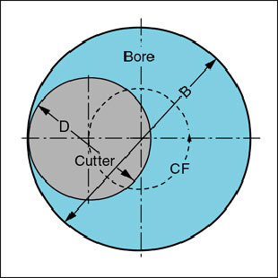
On square end cutters, the nominal cutting diameter (D) equals the effective cutting diameter (D eff), also known as working diameter (Dw). In cutters where the cutting edge is not square (ball nose, toroid, bull nose with larger radius, round insert tools, chamfer cutters, etc.) the working or effective cutting diameter, and with it the cutting speed, varies depending on the axial depth of cut used. Refer to picture below.
Using the nominal cutting diameter to calculate cutting speed and feedrate, the cutting speed and feed per tooth (chip thickness) is much lower if cutting at a shallow axial cutting depth. This impacts machining results negatively. The cutting speed should be calculated using the working or effective cutting diameter (Dw), which can be calculated for ball nose and toroid (and bull nose) cutters with the following formulas or taken from the reference tables below:
Since the feed per tooth (fz) or chip thickness is reduced through the effect known as chip thinning, the feedrate should be increased back up to the recommended chip thickness value, which will speed up the machining process. Reference tables for ball nose and toroid tools cutting at various axial depths of cut values and corresponding feedrate multipliers are shown above. We recommend using the tables to assure the tools will run at optimum performance values.
When milling 3D surfaces and shapes, the contact on ball nose cutters (the first choice of tools for these applications) will depend on the geometry of cavity or core. It can vary from tip to side cutting. The cutting speed may vary from the cutting speed calculated for the peripheral diameter to zero speed at the tip. In roughing, this problem can be overcome by machining with “Z-level” strategy; the cutting speed however has to be calculated for the “worst scenario”, i.e. the biggest diameter of engagement (Dw) of the cutter when it comes in contact with the steepest area of the cavity or sidewall. When finish milling, the best solution is to divide the cavity or core into separate shallow and steep wall segments or sections and calculate appropriate machining parameters and programs for each section.
Chip thinning occurs on cutters where the cutting edge is not square, i.e. parallel to the axis of the cutter. Tools that fall into this category are ball nose, toroid, bull nose with larger radius, round insert tools, chamfer cutters, etc. With the prevalent use of ball nose tools in the milling of dies and molds, chip thinning can become an important productivity-enhancing tool. Ball nose cutters cut with the radius of the ball, from the tip of the tool to the tangency point at full diameter. The cross-section of the chip produced by a ball nose cutter resembles a section of a crescent moon. The chip thickness when cutting at full radius axial depth equals the feed per tooth (fz). At shallower axial depth of cut the “crescent” is thinner, the chip thickness is less and the volume of material removed is also less. The aim is to machine with a constant chip thickness at various depth of cut (ap) in order to remove a constant, productive amount of material at various axial cutting depths. Chip thinning occurs in axial and radial direction.
Millstar has developed a simple formula that will calculate the approximate increase so that the mean chip thickness (hm) equals the feed per tooth (fz). The feedrate adjustment is calculated as follows:
This feedrate increase is very aggressive and should only be used when milling flat features such as cavity floors, etc. Reduce the feedrate when coming near steeper features or sidewalls, where contact conditions change.
There is a relationship of tool shank rigidity to extension length of the tool. With this relationship a depth of cut (ap or an) and machining allowance (rest stock) for milling can be established for different hardness levels of steel. The values in Table 35 are general and intended as a guideline for roughing and semi finishing. For finishing cuts smaller values may be called for, depending on step-over and finish quality requirements. For solid carbide ball end mills and ball insert technology steel tool shanks (with tool shank diameter = cutting diameter D) the depth of cut value as follows:
Hardness: | Depth | Extension to | Extension to | Extension to | Extension to |
< 45 HRc | ap | 0.1 – 0.12 x D | 0.1 – 0.12 x D | 0.05 – 0.06 x D | 0.02 – 0.025 x D |
< 50 HRc | ap | 0.1 – 0.12 x D | 0.08 – 0.09 x D | 0.04 – 0.06 x D | 0.018 – 0.02 x D |
< 55 HRc | ap | 0.08 – 0.10 x D | 0.05 – 0.06 x D | 0.025 – 0.03 x D | 0.015 – 0.02 x D |
> 55 HRc | ap | 0.05 – 0.06 x D | 0.04 – 0.05 x D | 0.015 – 0.025 x D | 0.012 – 0.02 x D |
* Note: we recommend the use of the stiffer solid carbide tool shanks in tool extension over 6 X D or in applications where a fine finish is of prime importance.
Step-over (ae) values for roughing and semi finishing depend on the machinability of the material to be machined, but generally are 4 – 6 times the depth of cut value (ae = ap x 5).
Surface roughness is measured in tool feed direction as well as in step-over or pitch direction. The formulae to calculate the theoretical cusp height (peak-to-valley) values are as follows:
For practical purposes, the width and length of the “bites” cut by each tooth of a ball nose tool per one cutter revolution should be equal and the surface should appear like the squares in a chessboard. If this condition exists, the elevated points known as “cusps” are equally distributed and make manual polishing easier. In some cases polishing can be eliminated altogether. The concept was first introduced by Makino Milling Machine Company as “Feed = Pitch” or “f=P”. It is illustrated in picture 36A below. This condition is achieved when the feed per tooth (fz) equals the pitch or step-over (ae): fz = ae. Advantages are the shortest machining cycle to achieve the desired finish, a smooth, multi-directional surface finish that is easy to polish, and increased geometrical accuracy and repeatability. Stiff, sharp tools with minimal run-out are a requirement to achieve good finish results. Millstar tools and inserts will assure success.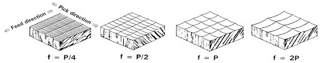
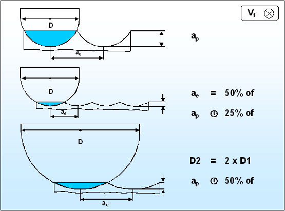
An additional consideration is the size of the ball nose tool radius vs. step-over distance and its influence on cusp height. The following illustration 36B will clarify the relationship.
The tooling choice for parting lines depends on the surface to be machined. If a flat parting line is required the tool of choice is Millstar’s TO toroid insert or TO solid carbide toroid tool. This will allow a larger step over to create the desired surface finish. The toroid tools work very successfully in hard and soft materials.
If the parting line is a contoured surface a ball tool is generally used. The type of ball tool will be determined by the material and hardness. Please refer to the aggressive milling charts to find out what type of insert in recommended for a particular material/hardness combination.
Helical boring can be used to rough or finish machine a particular bore. One of the advantages to this method is the ability to machine many different diameters with the same diameter tool. For example a .500” diameter tool can bore a diameter from .550” up to a .900” diameter. For roughing applications it is typically suggested to use a ball end tool with no more than .05” flute length. If the flute length is too long the tool will tend to deflect resulting in a taper in the hole. Normally climb milling is best suited for roughing applications. It is highly recommended to “ramp off” in an arcing motion when exiting the cut. Do not let the tool dwell when moving out of the cut. When finishing, the Millstar tools of choice are ball nose (RB), toroid (TO) and back draft (BD) style inserts depending on what features are required on the floor of the bore. Millstar’s solid carbide line of tooling can be used for smaller diameters as well but the tool will have to be relieved so that no more than .05” of flute length is available. An example of helical boring with a toroid insert tool is shown in the illustrations below.
Z-level milling can be explained as removing material to form a cavity or core by milling layer by layer (level by level) in X-Y contour continuous tool paths at constant Z-value step-downs. Each level is preferably milled in climb milling mode, entering the milling depth per layer by shallow linear or circular interpolation to the recommended Z-value depth for each layer. This allows the feedrate to remain the same as in the Z-level cut. We do not recommend plunging or peck drilling to depth. Preferably work from inside out to the periphery of the cavity in a climb milling (down milling) tool path. In the first pass the tool is engaged in a channel cut and the cutting edges are “in the cut” for 180 degrees. This imparts more heat into the tool, but the channel cut is relatively short. If instead working from the periphery toward the center, the peripheral first channel cut is far longer; the heat generated is higher and would require the tool to be run slower. The step-over or pitch (ae) for roughing and semi-finishing should follow Millstar recommendations. Typically the step-over in HS rough and semi-finish milling is 20 – 45 % of tool diameter. This keeps the cutting edge “in the cut” for a shorter time and gives the cutting edge less time to heat up. It also keeps the tool “on center” as it cuts on both sides of the tool’s axis and minimizes tool deflection.
At Millstar we highly recommend milling in Z-level mode with a ball nose insert tool. This includes cavities with shallow or steep angle as well as straight (perpendicular) walls. The large radius of a ball nose tool will be able to cut faster than square or bull nose tools; the ball nose insert will create a smoother transition and leave a more even stock for semi-finishing. Square and bull nose tools typically leave “steps” resulting in very uneven stock, causing changing machining forces and increased tool deflection for semi-finishing. Rest milling of small details (small radii, sharp corners, etc.) can be done with other tools once the cavity has been finished with the ball nose tool. We do not recommend drilling starting holes in corners or center of a cavity. They lead to interrupted cutting, possible chip re-cutting and additional cutter entries and exits during cutting, which lead to unnecessary thermal and load shocks on the cutting edge and tool life degradation.
The benefits of Z-level milling techniques include shorter machining cycles, simpler programming, less “cutting in air”, improved surface and geometric accuracy results, less manual polishing and better utilization of machine and cutting tools.
Millstar considers High Speed Machining (HSM or HSC) as a process and not as a particular cutting speed and feed rate. HSM can be performed at many different levels. Your machine, CAM system and cutting tool combination will determine the level where you will have success. HSM can be limited by any one of these variables. Material is not one of the variables that determine if you can perform HSM. It is true that some materials can be machined faster than others, but if you compare the HSM process to standard machining practices, using HSM will almost always be of advantage independent of the type of material. For example a cavity made of H13 hot work steel can be finished with a cutting speed of 2000 SFM (610 m/min.) or more, but a cavity made of D2 steel might only use a top cutting speed of 800 SFM (245 m/min.) for finishing. This is not to say the you are not performing HSM in the D2 material, if you compare this to conventional machining practices, where D2 is machined typically at 200-300 SFM (60 – 90 m/min.); increasing the cutting speed to 800 SFM (245 m/min.) is a dramatic increase in cutting speed and is considered HSM for this material. The entire process is needed to be able to perform HSM; it is a process where operations are performed with very specific, aggressive parameters and tools, but it is not limited to machine tools developed for HSM.
Typical of the HSM process are the benefits obtained with the process and techniques of HSM. The benefits include: shorter lead times and less production steps, often accomplished by combining roughing and semi-finishing as one hard milling operation; reducing or eliminating EDM and the need for electrode machining; accurate machining results to reduce polishing and try-out, etc.; response time reduction for the mold maker and his customer, the manufacturer of goods, since rapid model changes in almost all consumer goods are a fact of life and must be addressed to stay competitive.
Machine tools: higher spindle velocity and high centrifugal forces can lead to broken tool bodies or inserts being thrown off at bullet speeds. Safety enclosures with “bullet proof” windows are a must. High ramp up and ramp down speeds of spindle, lead screws and machine ways leads to faster wear and increased maintenance frequency.
Tool adapters and cutting tools: Use of balanced tools and adapters is necessary. Avoid using heavy or long tool/adapter combinations. Use only carbide cutting tools, do not use solid HSS end mills. Considerable care must be taken that cutting tools have minimal run-out. When HS milling soft and pre-hard steel, cutting edge run-out should be held to a maximum of 5% of the maximum recommended feed per tooth (fz) value; when HS milling through-hardened steel, the maximum run-out should be limited to 0.0004” / 0.01 mm. Milling with tools with more run-out can cause excessive strain on spindles, vibrations, and early tool breakdown.
Programming and process planning: It will be important to train programmers and machine operators in programming and process knowledge for HSM. They must “buy into the process”. Programming equipment, CAM software and high data transfer equipment are needed to reach the highest levels of HSM. Since it may be difficult to find experienced employees, training is important.
Safety issues: Most safety issues relate to cutting tools and guarding of the machine. Containing fractured tools safely within the machine enclosure, high cutting velocity and tool balancing are important safety issues. One international standard (ISO standard #ISO 15641 entitled “Milling cutters for high speed machining – Safety requirements”) covers cutters above a cutting speed (Velocity at maximum diameter of the cutter) above at 950 m / minute (approx 3,000 SFM). This speed translates to about 12,000 RPM on a 1 inch / 25 mm diameter cutter. We recommend putting HSM safeguards in place well below these values, particularly when using steel shank tools.
This depends on the type and hardness of the material to be machined. HSS/Cobalt cutting tools cannot be used for HS machining of Steel.Typically carbide is the cutting tool material of choice. The type of carbide tool will depend on the material and the process you wish to perform. In most die/mold High Speed machining, a carbide tool with AlTiN coating is the preferred tool. Millstar’s version of this coating is our TLN Exalon coating. The hardness of the material also plays a role in the selection of cutting tools. When machining soft materials under 45 HRc the choices are face mills, insert cutters and solid carbide tools. In harder materials the face mill is typically dropped from the list since accuracy, size and design do not allow these tools to be run at high cutting speeds.
Machines developed for HSM typically have high axis and spindle speed. The faster the top speed, the better? Not really. Fast rapid movements are only productive to a point. Fast rapid is fine if the move is from one point to a distant target point. To move from a point to another point close by, the high speed machine may not travel the short distance as fast as a machine with far slower top speed. The reason? It is acceleration and deceleration. The same drive motor can ramp up and down faster, if it is geared for a lower top speed. A slower machine may indeed cut parts with contour changes faster than a machine with higher top speed. Look for quick, agile machines with rapid acceleration and deceleration capability if you machine parts with smaller, more detailed features.
For the demands on machine tool, spindles and controls please see the section in FAQ’s entitled “Machine tool, spindle and CNC control considerations”.
The CAM system and CNC control play a vital role in the success of the HSM process. The program that is generated from the CAM system must be clean and accurate but also must be utilizing all of the processes needed to be successful. A CNC control with look-ahead and geometric intelligence capable of a high sustained feedrate is needed.
A capable CAM system will let you achieve a higher level of productivity. But how do you choose the right CAM system for your needs? Using CAM software benchmarks can compare performance, capability and functionality of CAM software. These tests however rely on simulations and are usually compared “on screen” only. To really test a CAM system for its usefulness and adequacy for your operation, it may be time well spent to run concrete simulation and machining trials on an actual part that represents the type of work you plan on doing. The trial should include 3-axis machining (and 3+2-axis if required) of a part prepared in advance. Specify the machining strategies you prefer to use, but let each CAM software supplier suggest alternatives to improve productivity, calculation time and machining quality results. Also test the accuracy, reliability and speed of reading CAD data from other systems. Compare machining time, calculation speed and simulation time, Make certain the software can complete the machining from start to finish and that there are no problems encountered with collisions, tool entry and exit strategies or macros. Also compare surface finish and geometric accuracy results. Further check that the software can support exclusion of areas, details or surfaces for later machining with a different tool, cutting strategy or special operation.
Next, let the software companies test on a cavity or core for which you give them the geometric model. Let the software companies generate the machining program. Compare results using the same criteria as above.
Desirable features to look for in a CAM system for milling include the following:
- The CAM system must have a CAD functionality to detect any surface defects, and eliminate or correct them.
- Milling techniques and strategies for conventional and High Speed machining, including “NURBS” machining.
- Automatic breakdown of the part geometry into steep and flat areas should be possible, to take advantage of a different machining strategy for each.
- Uniform roughness and remaining stock for finish path in HSM should be achieved. Various machining strategies should be available to machine remaining stock in steep and flat areas, fillets, along flanks, X-Y-parallel and contour-parallel.
- Roughing strategies, particularly Z-level contour-parallel and Z-level axis-parallel milling is needed.
- Curve machining should be available, which includes moving a tool along a generated curve to round off corners or “pencil trace” fillets.
- The CAM system should support these 3-axis and 3+2-axis cutting strategies:
- Bi-parallel machining of surfaces with curves should be a feature, to smoothly generate transitions between two curves.
- Isoparametric milling for constant special tool path generation is a plus.
- Z-Level cavity/core milling is a very important feature.
- Raster or bi-directional flat and contoured surface machining is a must.
- Helical and/or linear ramp engagement into the material, and helical machining and helical boring macros are essential.
- The ability to set program tolerances as low as .00004 / 0.001 mm correctly will allow for best finishing results.
- Corner picking and residual stock machining capabilities are required for economical rest machining.
- The system must allow the use of square, bull nose, toroid and ball nose cutters.
- The system should have an easy-to-use interface and have a clear graphical display to ensure the system is easy to use and is quickly learned.
A capable CAM system right for your operation will let you go from a steel block or casting to mirror-finished surfaces and accurate, reproducible machining results. In addition the processing and machining time as well as secondary polishing time will be greatly reduced.
In one word, definitely!Millstar considers HSM as a process, not just a combination of high RPM and feedrate. The age and capabilities of the machine will only limit the success of HS machining, it will not determine whether or not you can perform HSM.
Millstar has many customers that have 10 year old, or older, machines. These machines were never designed for HSM and typically have maximum spindle speed of 4,000 RPM. These machines can typically perform well at feedrates to 80 IPM (2,000 mm/min.) without noticing any negative effects. If the proper process is used, 80 IPM can used to perform roughing and finishing operations. The normal limitation to the older machines is program storage size. DNC is normally used to drip feed the program to these controls. If DNC is not available you can break up the program into sections and load each section individually into the control and run one section at a time.
Yes, if the proper processes are followed. Millstar has successfully performed HSM in materials up to 68 HRc. The Millstar tooling required is a non-chip breaker insert with TLN Exalon coating or any of the Moldstar solid carbide tools. For more details please go to our applications data page and review the test cut for 68 HRc M4 material. This was an actual test cut performed at the plant of a customer. The customer is machining these cavities on a daily basis.
In many cases HSM can replace the EDM process. One determining factor is length to diameter ratios. Another factor is the capability of the cutting tool to machine difficult to reach features on the part. Try to avoid unpredictable situations. Can the tool reach the feature to be machined? Can it machine a severe undercut or reverse taper? Can it mill a very narrow, very deep slot? If it cannot do so predictably, EDM may be the only answer.
HSM can be used successfully to a tool extension ratio of approximately 10 X Diameter of cutter, and in some cases longer. If a cavity has sharp corners deep inside this feature may still need to be machined with an EDM process. In applications where components have features with high detail, a combination of HSM and EDM can be used to obtain the best overall economy and lead-time.
For a quick answer to this question go to our aggressive milling charts under the Application Data area of our web site.Parameters for milling through-hardened steel are listed along with insert or tool recommendations. If further information is required, please contact our applications staff; we will help develop a process for your particular part.
Mold and die steels are chosen by the intended use of the mold or die. Some of the characteristics are:
Type of die or mold: Hot working for metal forging, die casting, extrusion. Cold working for cold forming, draw dies, cold upsetting and forging, cold extrusion, blanking, shearing, stamping. A specialty area in mold making is plastic processing such as injection molding, extruding, blow molding, vacuum forming, compression and transfer molding, rotary molding, etc. where steels with special characteristics are required.
Size of mold or die: Larger molds or dies are usually made from pre-hard steels available from steel suppliers in different hardness ranges. Rough and semi finish machining is done at this level of hardness; the component will be heat treated as needed for the application and then finished in the fully hardened state. Smaller dies and molds can be machined in the fully through-hardened state by hard milling, EDM machining or a combination of the two processes. Hardness of plastic injection molds generally depends on the number of parts the mold is expected to produce. Short run molds for production not exceeding 100,000 parts can be made from annealed soft steel under 250 HB / 25 HRc. Medium production molds (under 1,000,000 parts) are usually made from pre-hardened steel at 28 – 45 HRc and long run molds (over 1,000,000 parts) are made from high hardness steel at 48-65 HRc.
Mold or die material properties: Cold Work steel (O1, S1, A2, D2, S7, M3 Class 3), Hot Work steel (H11, H13) and Mold steel (P20, SS-420) are popular in the US. A comparison of international equivalent steels available is shown in table 1A below. Specialty steel makers have also developed alternate proprietary steels with special properties that are achieved with processing methods including balanced deoxidation, vacuum arc degassing (VAD) or vacuum arc remelting (VAR), resulting in dense, uniform and clean steels. Some of the special properties include polishability to optical or lens quality finish, increased wear and corrosion resistance, better machinability, and resistance to deformation, uniform hardness, etc.
U.S.A |
Germany |
Japan |
Sweden |
Great Britain |
Italy |
Spain |
France |
AISI / SAE |
W. Nr. | JIS | SS | B. S. | UNI | UNE | AFNOR |
L 3 | 1.2067 |
| - | BL 3 | - | F.5230 | Y 100 C 6 |
D 3 | 1.2080 | SKD 1 | - | BD 3 | X 205 Cr 12 KU | F.5212 | Z 200 C 12 |
L 2 | 1.2210 | - | - | - | 107 CrV 3 KU | - | - |
H 10 | 1.2365 | - | - | BH 10 | 30 CrMoV 12 27 KU | F.5313 | 32 DCV 28 |
H 11 | 1.2343 | SKD 6 | - | BH 11 | X 37 CrMoV 5 1 KU | F.5317 | Z 38 CDV 5 |
H 12 | 1.2606 | SKD 62 | - | BH 12 | - | - | Z 35 CWDV 5 |
H 13 | 1.2344 | SKD 61 | 2242 | BH 13 | X 40 CrMoV 5 1 1 KU | F.5318 | Z 40 CDV 5 |
A 2 | 1.2363 | SKD 12 | 2260 | BA 2 | X 100 CrMoV 5 1 KU | F.5227 | Z 100 CDV 5 |
D 2 | 1.2379 | - | - | BD 2 | X 155 CrVMo 12 1 KU | - | Z 160 CDV 12 |
O 1 | 1.2510 | - | - | BO 1 | 95 MnWCr 5 KU | F.5220 | 90 MWCV5 |
S 1 | 1.2542 | - | 2710 | BS 1 | 45 WCrV 8 KU | F.5241 | - |
L 6 | 1.2713 | SKT 4 | - | - | - | - | 55 NCDV 7 |
O 2 | 1.2842 | - | - | BO 2 | 90 MnVCr 8 KU | - | 90 MV 8 |
T 15 | 1.3202 | - | - | BT 15 | - | F.5563 | - |
M 42 | 1.3247 | - | - | BM 42 | HS 2-9-1-8 | F.5617 | Z 110 DKCWV 09-08-04-02-01 |
M 3 Cl. 2 | 1.3344 | SKH 52; SKH 53 | - | - | - | F.5605 | Z 120 WDCV 06-05-04-03 Z 130 WDCV 06-05-04-04 |
M 7 | 1.3348 | - | 2782 | - | HS 2-9-2 | F.5607 | Z 100 DCWV 09-04-02-02 |
4140 | 1.2312 | - | - | - | - | F.5304 | 40 CMD8+S |
304 | 1.4301 | SUS 304 | 2332 | 304 S 15 | X 5 CrNi 18 10 | F.3541 | Z 6 CN 18.09 |
310 | 1 4841 | SUH 310 | - | - | X 16 CrNiSi 25 20 | F.3310 | Z 12 CNS 25 20 |
318 | 1.4583 | - | - | - | X 6 CrNiMoNb 1713 | - | - |
420 | 1.4021 | SUS 420 J1 | 2303 | 420 S 37 | X 20 Cr 13 | F.3402 | Z 20 C 13 |
Please note: the standard numbers in Table 48A are shown only as a general comparison guide. For the most accurate information please refer to the information in each country’s published Standards and to the complete information available from the individual steel suppliers.
The content of alloy elements in and chemical composition of steel is important. Generally, the higher the alloy content the more difficult the steel is to machine. Listed below are some of the more important alloy elements and their specific influence on the properties of steel. The information is general in nature and intended to give the reader a basic understanding. The presence of several alloy elements may increase or change the influence of one or more elements. The presence of the alloy elements are only the prerequisite for the desired influence on steel properties; only the heat treatment of the steel will result in the change to the desired properties.
C CARBON
Carbon is the most important and influential alloy element in steel. Aside from Carbon, all steels naturally contain Silicon, Manganese, Phosphorus and Sulphur. An intentional increase in Silicon and Manganese as well as the addition of alloying elements leads to alloy steel. Increased Carbon content increases the mechanical strength and hardening properties, but elasticity, forging, cutting and welding properties are reduced. Carbon content has no significant influence on corrosion resistance to water, acids and hot gases.
Co COBALT
Cobalt hinders grain growth, improves the resistance to tempering and improves hot tensile strength; it is often present in High Speed (HS) tool steel, hot work steel and heat resisting materials. It does not form carbides. It promotes graphitic formation. It increases residual magnetism and thermal conductivity.
Cr CHROMIUM
Increases hardness and strength. Only minimally reduces elasticity. Improves resistance to heat and non-scaling properties. With higher Chrome content the steels become more corrosion resistant and with Carbon forms high wear resistant Carbide. Welding properties deteriorate with increased Chromium content. It is a strong Carbide former. The tensile strength of steel rises by 80-100N/mm2 per 1% Cr. The yield point is likewise increased; the notch impact value is lowered.
Mo MOLYBDENUM
Molybdenum increases tensile strength and heat resistance and is often found in hot working steels. It has a favorable influence on welding properties. Steel with a higher Mo content tends to be difficult to forge. It has a strong tendency to form Carbides. Mo is alloying element of choice in HS tool steels, hot working steels, case hardening and heat-treating steels, heat resistant and austenitic corrosion resistant steels.
NI NICKEL
Nickel increases the strength of steels less than Silicon and Manganese, with elasticity only lowered slightly. Ni improves through hardening, especially if the steel also contains Chromium. Chrome-Nickel steels are considered stainless and are heat and scaling resistant. Nickel does not impair welding properties.
V Vanadium
A small alloy addition improves hot hardness and reduces grain growth. Vanadium acts especially favorable in tool and structural steels. Vanadium is a strong carbide former and increases tensile strength and yield point, and in particular the hot hardness properties.
TU (W) Tungsten (Wolfram)
Tungsten improves the strength properties and increases hardness and cutting edge life substantially. It improves heat resistance values. The tensile strength and yield point values are increased by about 40N/mm2 per 1% Tu. It is used primarily in HS tool steels and in steels requiring high hot hardness and steels of highest hardness.
Fully hard steel is usually classified as steel above 45 HRc to 68 HRc. Standard milling cutters with carbide cutting inserts are not usually applicable in this hardness range. Millstar has developed cutting technology including solid carbide end mills, carbide inserts, tool holders and application parameters that allow for economical machining of steels in this hardness range. High hard molds, extrusion dies and similar components, which previously needed to be machined by grinding or EDM methods, can now be milled. By replacing EDM significant time and cost savings are achieved.
The composition of steel and alloying elements is discussed in a separate question on the properties of steel. The higher the carbon content of steel, the lower the machinability. The hardness is also of primary importance. Conventional tools can be used to 45 HRC. Up to 68 HRc carbide tools and inserts specially designed for this purpose can be used. Above this hardness CBN and ceramic tools find limited use; grinding and EDM methods are other alternatives.
The structure of steel is important as well. Wrought, rolled and extruded steel, particularly if subsequently surface machined and annealed, will be somewhat easier to cut. Castings and compacted forgings, which often contain non-metallic inclusions (Sand, aluminum oxide) or have surface skin, can prove difficult to machine.
Ti6Al4V (TiAl6V4) is the most commonly used Titanium alloy in industry. Millstar has developed machining strategies, catalog standard tools and parameters that will allow Titanium to be profile milled very successfully. Use standard or High Speed machining strategies. The tools best suited are the versatile standard catalog solid carbide end mill series from Millstar, and the Millstar insert technology tools. Use of inserts with chip-breaker geometry is recommended.
When machining Titanium, a certain amount of lubricant is of advantage in preventing abrasive wear and adhesion. Coolant with a higher coolant concentration (9-12%) or MQL is recommended.
Tough to machine Aerospace materials such as Inconel, Hastelloy, Waspaloy, etc. can be successfully profile machined with conventional and High Speed machining strategies. The tools best suited are the versatile standard catalog solid carbide end mill series from Millstar, and the Millstar insert technology tools. Use of inserts with chip-breaker geometry is recommended. For softer, gummy or sticky materials such as stainless or lower carbon steels, and for aerospace materials like Titanium, Inconel, Hastelloy, Waspaloy Millstar has developed a thin-film coating that minimizes edge build-up and can perform under extreme conditions and with long tool life. When machining these materials a certain amount of lubricant is of advantage in preventing edge build-up, abrasive wear and adhesion. Coolant with a higher coolant concentration (9-12%) or MQL is recommended.
Stainless steels AISI series 300 (Chrome-Nickel alloys), AISI series (Chrome and Chrome-Molybdenum alloys) and precipitation-hardening (PH) steels can be profile milled with strategies, parameters and catalog standard tools developed by Millstar for profile milling.
400 series stainless steels in soft and hardened state have very good machinability properties when using Millstar tools. 300 series stainless steels and PH steels are not quite as easy to machine, but HS machining methods can still be employed. Resulfurized material machines easiest. For softer (<40 HRc), gummy or sticky materials such as stainless or lower carbon steels, Millstar has developed a thin-film coating that minimizes edge build-up and can perform under extreme conditions and with long tool life. When machining these softer, gummy or sticky materials a certain amount of lubricant is of advantage in preventing edge build-up and adhesion. Coolant with a higher coolant concentration (9-12%) or MQL is recommended. Running tools aggressively, so the temperature in the cutting zone is high enough to prevent built-up edge eliminates this problem and increases productivity as well.
All stainless steels above 40 HRc should be machined with non-chipbreaker geometry when using inserts in this hardness range. Use of MQL or compressed air is recommended.