
Millstar: Tech Articles
The Quad Force Machining Challenge
All manufacturers in the metal machining industry face the same cutting tool dilemma.
All manufacturers in the metal machining industry face the same cutting tool dilemma. That is, determining what machining processes to adopt while keeping cutting tool inventory and cost under control. The balance of cost versus productivity does not always yield the best possible manufacturing solutions or allow for the latest in cutting tool technology. Some manufacturers make production sacrifices to minimize cutting tool inventory and control machining costs. Others may inventory unnecessary cutting tools knowing it is not important to their process. Fortunately, forward thinking cutting tool manufacturers are developing technology to ease this dilemma. The new Quad Force cutting tool geometry (QFM) provides machinists and programmers the flexibility to perform multiple machining applications with one tool. For example, the Quad Force geometry is a hybrid combination of high feed geometry, variable flute geometry, variable helix geometry and offset geometry. This provides the flexibility to side/slot mill, high feed mill, trochoidal mill and plunge/variable plunge mill with one tool. It is not difficult to see the cost savings when you raise your expectations of cutting tool flexibility. The Quad Force geometry and machining strategy can increase productivity by removing the need for tool changes or changes in strategy. It can also remove the need to inventory multiple cutting tool geometries without sacrificing production capability. In fact, by properly utilizing the Quad Force cutting tool geometry, you can reduce the amount of cutting tools you purchase. Quad Force (QFM) will force programmers and machinists to challenge their machining processes and the way they currently evaluate tooling.
The Quad Force Geometry
The natural progression in chip making technology is the Quad Force (QFM) geometry. With recent advancements in five- and six- axis grinding technology, geometries available on carbide cutting tools have become limitless. The increased grinding technology has made the newer high performance cutting tool geometries possible. However, the time has come to let technology drive innovation in cutting tools again. The Quad Force (QFM) geometry is finally addressing the high performance roughing gap. Regardless of the industry jargon, most roughing applications can be attributed to high feed, variable flute, variable helix or an offset. Now with Quad Force (QFM) geometry, a single cutting tool exists as a hybrid combination of the previously listed geometries with all of the manufacturing capability included. Programmers and machinists have the flexibility of choosing the best possible roughing process with a fraction of the cutting tooling library. The Quad Force (QFM) cutting tool geometry is capable of performing high feed machining, trochoidal machining, side/slot milling and plunge/variable plunge milling. To properly utilize this flexibility to increase productivity, programmers and machinists must adopt a Quad Force Machining strategy. Flexibility without purpose will not yield productivity. Adopting a Quad Force Machining strategy to utilize the Quad Force (QFM) cutting tool geometry is the first step to boost your machining productivity.
The Quad Force Machining Strategy
With CAM software advancements, cutting tool manufacturers are forced to provide complimentary solutions. Whether it’s volume milling, vortex milling or rough machining, manufacturing capabilities are rapidly increasing. Incorporating these increased capabilities into your machining strategy is important to see the true benefits. Beautiful tool paths without cutting tool technology will not produce the productivity boost for which you have already paid. To illustrate this capability, Figures 1-4 show volume milling by Cimatron. This process would normally use two or three tools, and require multiple spindle speed and feed rate changes. By using a Quad Force Machining strategy, the same application was achieved with one tool at constant spindle speed and feed rate.
This machining application was divided into a Quad Force Machining strategy to illustrate the range of capabilities, time savings and cost reduction. The Quad Force (QFM) cutting tool geometry versatility often eliminates the need for a re-roughing operation. The flexibility to switch between machining applications without a tool change increases the “in the cut” time. Furthermore, being able to choose between the combined geometries allows you to select the process with the highest metal removal rate. This choice flexibility often allows programmers and machinists to use a smaller diameter tool, which yields a true “net shape” machining solution. This flexibility in machining strategy can be applied to limitless part geometries, most material types, any machine tool and any industry.
|
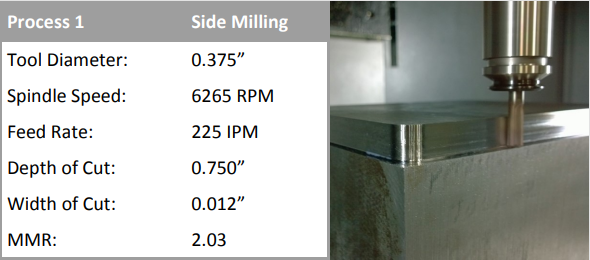
Figure 1 - Side / Slot Milling
The variable helix portion of the Quad Force (QFM) geometry makes it capable of straight wall or side milling. This process uses a shallow width of cut with a large depth of cut. The tool engagement is combined with an aggressive chip load to produce 2 cubes per minute metal removal rate on a 3/8-inch diameter tool. By correctly managing the tool engagement, this machining strategy allows programmers and machinists to switch between applications at constant spindle speed and feed rate.
|
|
|
|
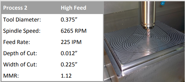
Figure 2 - High Feed Machining
The high feed geometry portion of the tool allows for high metal removal rates on contoured or complex 3D shapes. In Process 2 the tool engagement changes from a large depth of cut with a small width of cut to a small depth of cut with a large width of cut. This illustrates a high feed machining application at constant spindle speed and feed rate of Process 1. The flexibility of the Quad Force (QFM) geometry to switch between tool en- gagements at constant spindle speed and feed rate will increase “in the cut” time. |
|
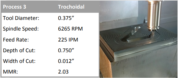
Figure 3 - Trochoidal Milling
The variable flute geometry portion allows for high performance trochoidal roughing. Combined with the highfeed and offset geometry it allows for helical boring. In Process 3 spindle speed and feed rate remain constant. A 0.750-inch depth helical bore at 3 degrees into solid stock with a 0.3750-inch diameter tool allows the tool to switch to trochoidal milling without exiting the part. Once again the tool has changed from a small depth of cut with a large width of cut to a large depth of cut with a small width of cut engagement without a tool change. This is a great example of the true flexibility of the Quad Force (QFM) geometry. |
|
|
|
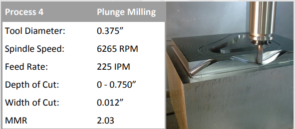
Figure 4 - Plunge / Variable Plunge
The Quad Force (QFM) geometry with offsets aids in variable plunge milling. Process 4 illustrates a variable plunge mill that creates a contour by surface milling. The tool is able to switch between a small depth of cut with a large width of cut and large depth of cut with small width of cut engagement. The Quad Force (QFM) geometry will plunge and variable plunge at the same feed rates and spindle speeds as the other three processes. |
Summary
The above examples have shown the range of applications for the QFM geometry and a Quad Force Machining strategy. The production and manufacturing benefit of this cutting tool geometry is flexibility. The flexibility to choose the best possible manufacturing process with a fraction of the tooling library. This new multiple application hybrid cutting tool geometry can be applied to most materials in any metal machining industry. By raising your expectation on tooling flexibility, a Quad Force Machining strategy can increase your productivity. This trend in cutting tools will force programmers and machinists to challenge their machining processes and the way they currently evaluate tooling.
For a complete explanation and actual test cut video, please visit http:// www.youtube.com/user/mymillstar.